Working Principle
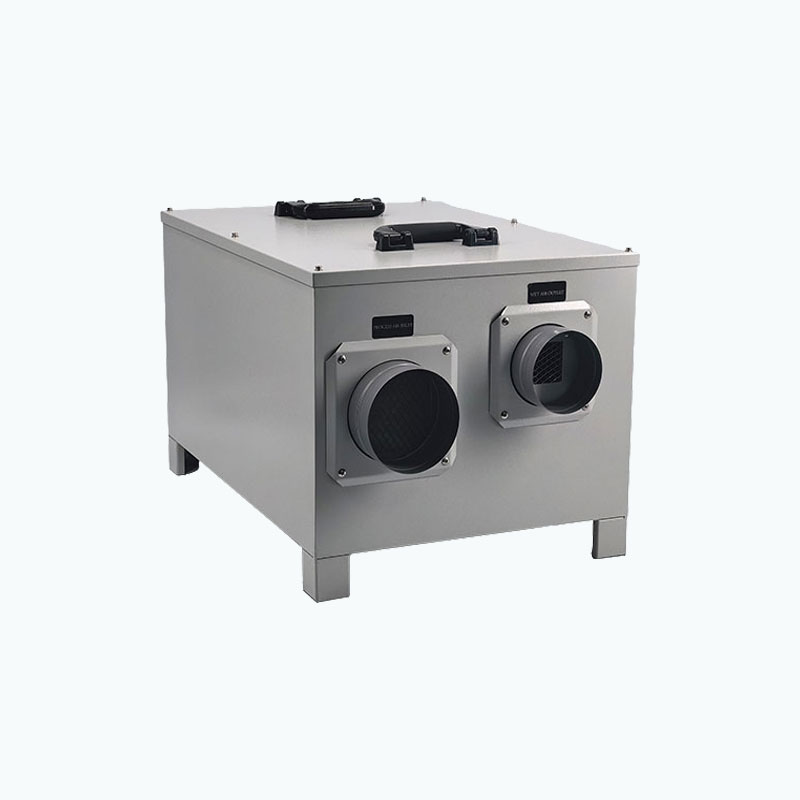
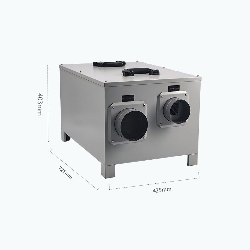
The dehumidifier uses separate process air and reactivation air circuits for continuous moisture removal.
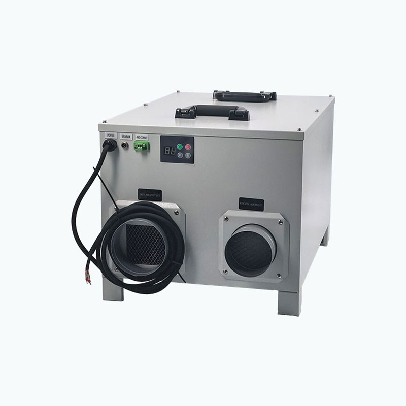
- Process Air: Humid air passes through the G4 filter and desiccant wheel. Moisture is adsorbed, and the process air fan delivers dry air through the outlet.
- Reactivation Air: Fresh air passes through a separate G4 filter and is heated before entering the regeneration section of the wheel.
- Moisture Exhaust: The reactivation fan carries released moisture out through the regeneration air outlet.
- Continuous Regeneration: The rotating wheel continuously switches between adsorption and regeneration, maintaining stable dehumidification.
Product Parameters
| Model | Dehumidification Capacity (20°C, 60% RH) | Power Supply | Rated Power | Rated Current | Process Airflow |
| MCH-350XF-02 | 2.5 kg/h | AC 220V / 50Hz | 2000 W | 9 A | 400 m³/h |
| Reactivation Airflow | Process Air External Static Pressure | Reactivation Air External Static Pressure | Process Air Duct Diameter | Reactivation Air Duct Diameter | Desiccant Rotor Size |
| 130 m³/h | 110 Pa | 85 Pa | Φ120 mm × 2 | Φ100 mm × 2 | 250 × 100 mm |
| Filtration Device | Operating Temperature | Dimensions (L×W×H) | Weight | Humidity Setting Range | Designed Service Life |
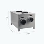
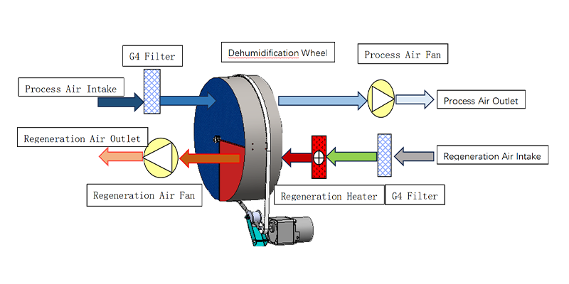
| Primary Filter | -10°C–50°C | 721 × 425 × 403 mm | 45 kg | 5%–95% RH | ≥ 10 Years |
Manufacturing Quality Control
Material & Welding
Uses 1.0 mm sheet metal and ER70S-6 welding wire. Welds are uniform and free from pores, slag inclusions, and cracks.
Precision & Surface Finish
Post-weld flatness is controlled within ≤ 1.0 mm, with weld areas polished to Ra ≤ 3.2 μm. Dimensional tolerances follow GB/T 1804-m.
Strength & Assembly
Structural strength reaches ≥ 350 MPa. Component gaps are controlled within ≤ 0.5 mm, with overall flatness within ≤ 1.5 mm.
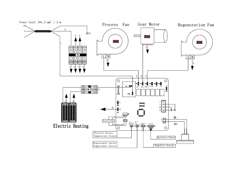
Circuit Diagram