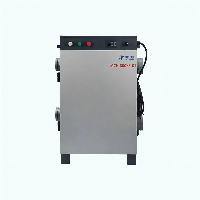
Working Principle
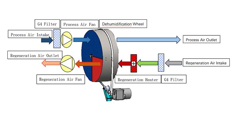
1. Process Air Drying
Humid air is filtered, driven by the process fan, and passed through the desiccant wheel to remove moisture.
2. Dry Air Delivery
The treated low-humidity air is discharged through the process air outlet.
3. Reactivation Air Heating
A separate reactivation air stream is filtered and heated before entering the regeneration section of the wheel.
4. Rotor Regeneration
The heated air removes stored moisture from the desiccant material.
5. Moisture Exhaust
The regeneration fan discharges the moisture-laden air outside, allowing the wheel to continuously repeat the drying cycle.
Product Parameters
| Model | Dehumidification Capacity | Test Conditions | Power Supply | Rated Power | Rated Current |
| MCH-800XF-01 | 120 L/day | 20°C, 60% RH | 380V / 50Hz | 9 kW | 18 A |
| Process Airflow | Reactivation Airflow | Process Air External Static Pressure | Reactivation Air External Static Pressure | Process Air Duct Diameter | Reactivation Air Duct Diameter |
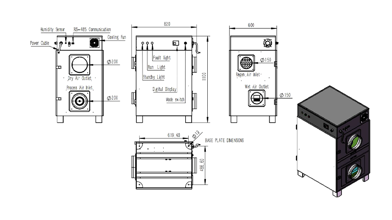
| 880 m³/h | 350 m³/h | 250 Pa | 130 Pa | Φ200 mm × 2 | Φ150 mm × 2 |
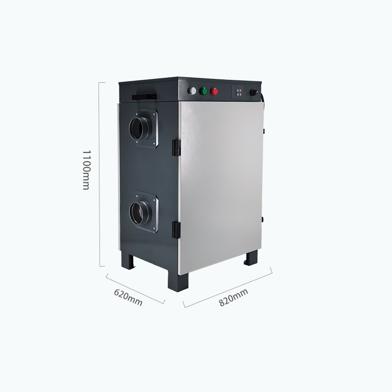
| Desiccant Rotor Size | Filtration Device | Operating Temperature | Dimensions (L×W×H) | Weight | Humidity Setting Range |
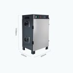
| 450 × 100 mm | Primary Filter | -10°C–50°C | 820 × 600 × 1100 mm | 110 kg | 5%–95% RH |
Manufacturing Quality Standards
| Base Material | Welding Wire | Weld Quality |
| SPCC cold-rolled steel sheet | ER70S-6 | Uniform, free from pores, slag inclusions, and cracks |
| Post-Weld Flatness | Surface Finish | Dimensional Tolerance |
| ≤ 1.0 mm | Ground flush and polished to Ra ≤ 3.2 μm | GB/T 1804-m; post-weld length tolerance ±1 mm |
| Epoxy Primer Coating | Structural Strength | Assembly Accuracy |
| 20–30 μm after welding | ≥ 350 MPa | Component gap ≤ 0.5 mm; overall flatness ≤ 1.5 mm |
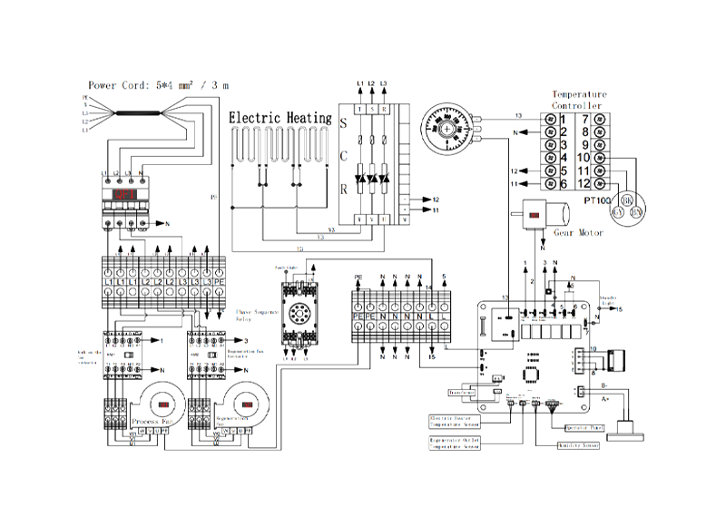
Circuit Diagram