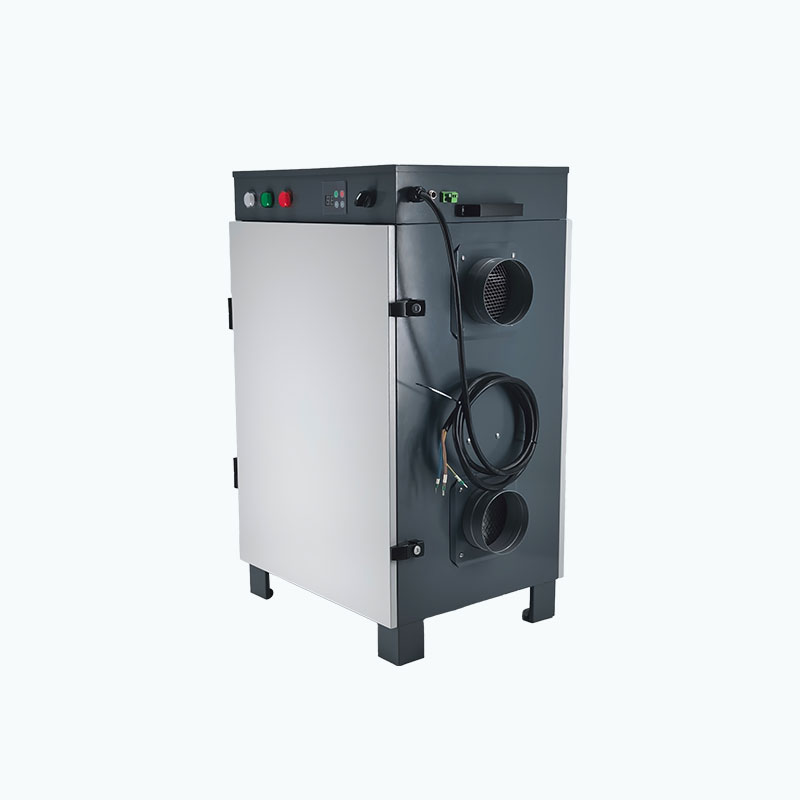
Working Principle
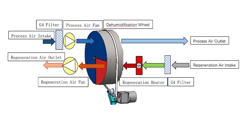
Process Air Path
- G4 Filter → Process Air Fan → Desiccant Wheel → Dry Air Outlet
- Humid air is filtered and driven through the desiccant wheel, where moisture is adsorbed before dry air is supplied.
Reactivation Air Path
- G4 Filter → Regeneration Heater → Desiccant Wheel → Regeneration Air Fan → Moist Air Outlet
- Reactivation air is filtered and heated to remove moisture stored in the wheel, then discharged outside.
Continuous Dehumidification
The desiccant wheel rotates continuously between the process and regeneration zones, allowing simultaneous drying and regeneration.
Product Parameters
| Model | Dehumidification Capacity (20°C, 60% RH) | Power Supply | Rated Power | Rated Current | Process Airflow |
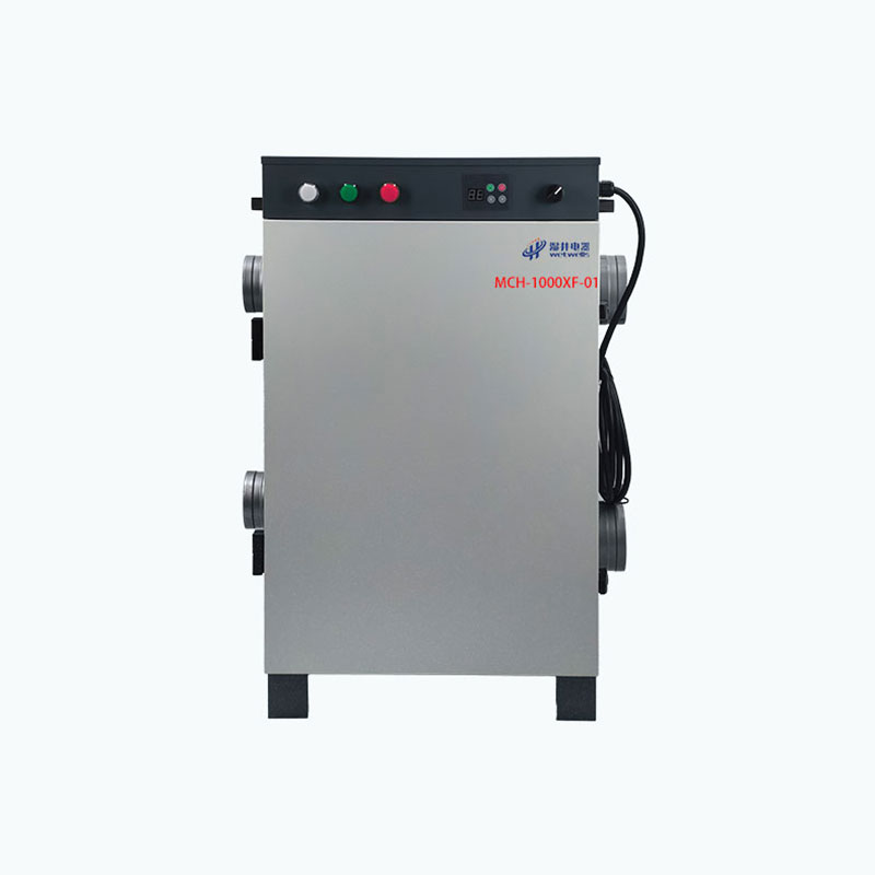
| MCH-1000XF-01 | 192 L/day | 380V / 50Hz | 11 kW | 24 A | 1100 m³/h |
| Reactivation Airflow | Process Air External Static Pressure | Reactivation Air External Static Pressure | Process Air Duct Diameter | Reactivation Air Duct Diameter | Desiccant Rotor Size |
| 400 m³/h | 295 Pa | 160 Pa | Φ200 mm × 2 | Φ150 mm × 2 | 450 × 100 mm |
| Filtration Device | Operating Temperature | Dimensions (L×W×H) | Weight | Humidity Setting Range | Designed Service Life |
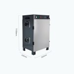
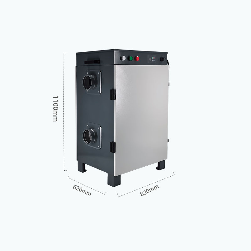
| Primary Filter | -10°C–50°C | 820 × 600 × 1100 mm | 110 kg | 5%–95% RH | ≥ 10 Years |
Structure & Control Design
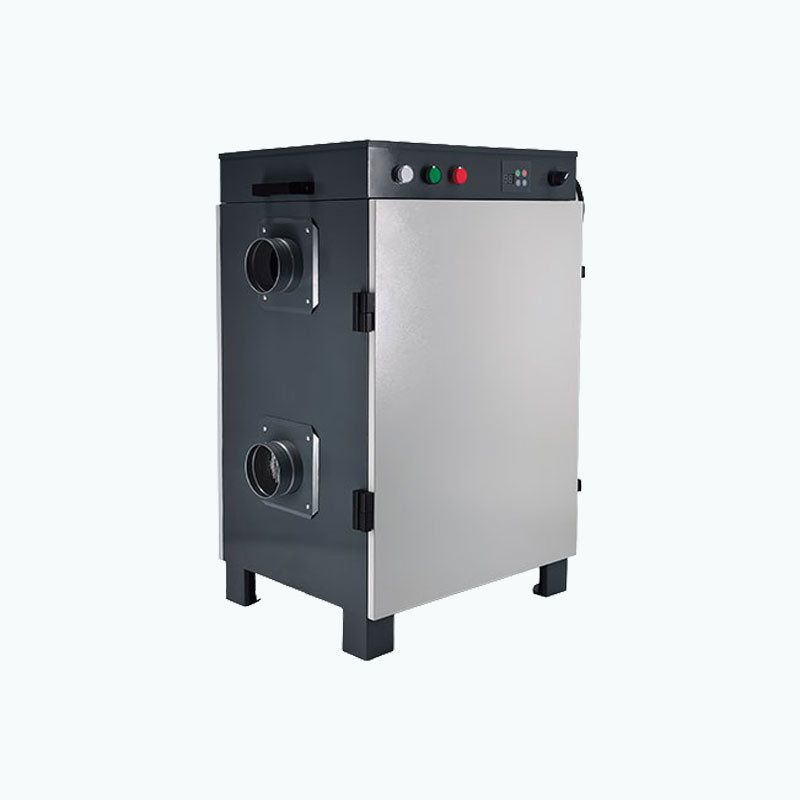
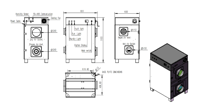
- Airflow Connections: Ø200 mm process air inlet and dry air outlet, with Ø150 mm reactivation air inlet and wet air outlet.
- Smart Monitoring: Built-in humidity sensor, digital display, and RS-485 communication support real-time monitoring and system integration.
- Operating Status: Run, standby, and fault indicators provide clear equipment status.
- Stable Installation: Ø12 base mounting holes and a vertical 820 × 600 × 1100 mm structure support secure installation.
- Internal Cooling: Integrated cooling fan helps maintain stable operating conditions.
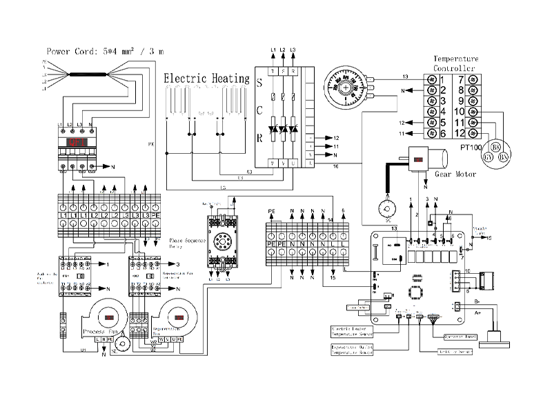
Circuit Diagram