Working Principle
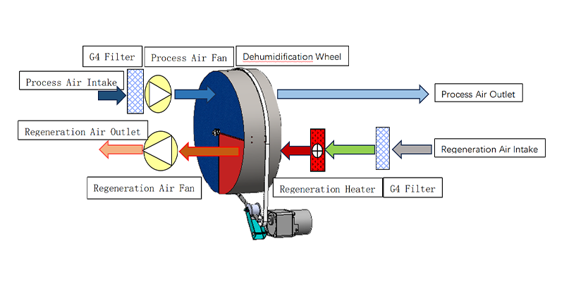
The system operates with two independent air circuits to achieve continuous dehumidification.
Process Air Circuit:
Humid air is filtered and pushed through the desiccant wheel, where moisture is adsorbed. The dried air is then supplied through the process air outlet.
Regeneration Air Circuit:
A separate air stream passes through the G4 filter and regeneration heater before entering the wheel. The heated air removes stored moisture from the desiccant material.
Continuous Operation:
The regeneration fan discharges the moisture-laden air, while the wheel keeps rotating between drying and regeneration zones for uninterrupted humidity control.
Product Parameters
| Model | Dehumidification Capacity (20°C, 60% RH) | Power Supply | Rated Power | Maximum Power | Rated Current |
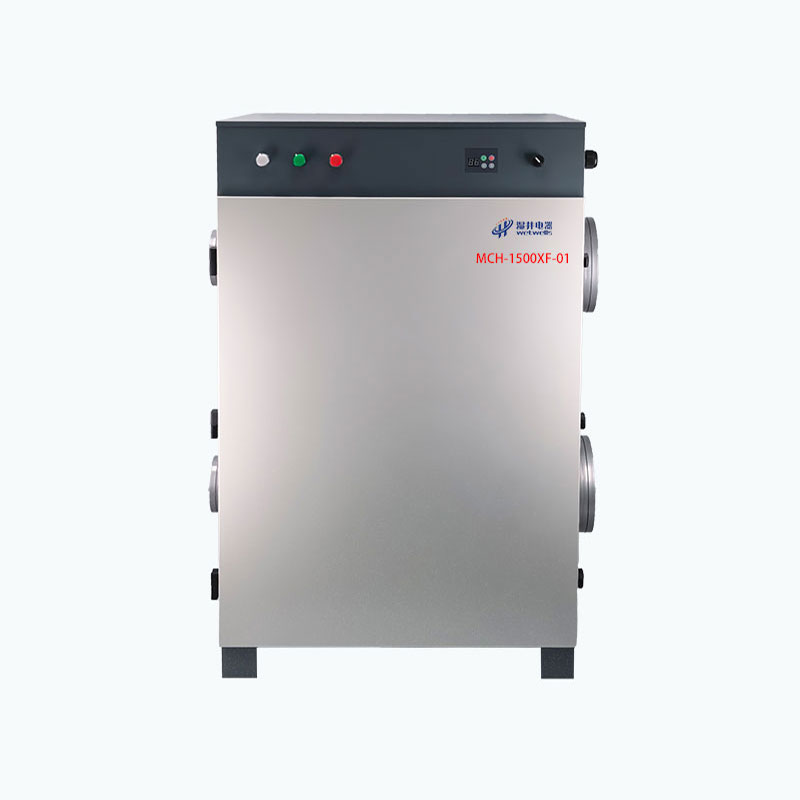
| MCH-1500XF-01 | 240 L/day | 380V / 50Hz | 15 kW | 16 kW | 28 A |
| Process Airflow | Reactivation Airflow | Process Air External Static Pressure | Reactivation Air External Static Pressure | Process Air Duct Diameter | Reactivation Air Duct Diameter |
| 1580 m³/h | 550 m³/h | 380 Pa | 230 Pa | Φ250 mm × 2 | Φ150 mm × 2 |
| Desiccant Rotor Size | Filtration Device | Operating Temperature | Dimensions (L×W×H) | Weight | Humidity Setting Range |
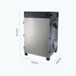
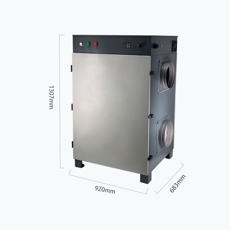
| 570 × 200 mm | Primary Filter | -10°C–50°C | 920 × 683 × 1307 mm | 210 kg | 5%–95% RH |
Product Structure & Control
Airflow System
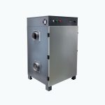
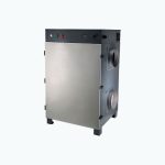
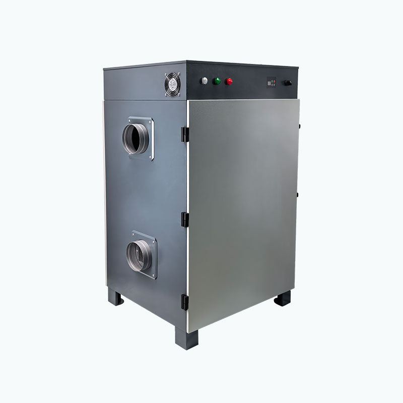
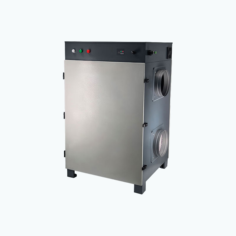
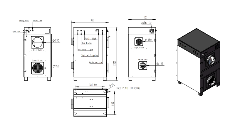
- Process air inlet / dry air outlet: Ø250 mm
- Reactivation air inlet / wet air outlet: Ø150 mm
- Designed for higher-volume ducted dehumidification systems
Monitoring & Communication
- Built-in humidity sensor
- Digital display for operating information
- RS-485 communication for system integration and remote monitoring
Operating Control
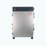
- Run / Standby / Fault indicator lights
- Integrated mode switch
- Built-in cooling fan for stable internal operation
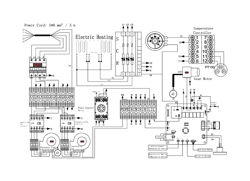
Circuit Diagram