
Design ceiling air distribution for indoor swimming pools by calculating moisture and ventilation loads, then placing outlets to protect glazing, serve occupied zones, and limit disruptive water-surface drafts.
Coordinate returns, outdoor exhaust, dehumidification, and controls as one system. Verify performance through airflow balancing, pressure checks, and condensation monitoring during operation.
Start With the Pool Room, Not the Diffuser Catalog
Ceiling outlets are the visible end of a larger design. Before selecting them, establish what each air path must achieve under occupied, unoccupied, heating, and cooling conditions.
Record pool dimensions, deck widths, ceiling elevations, glazing areas, and likely obstructions. Beams, suspended lighting, and spectator platforms can interrupt otherwise convincing airflow layouts.
Define how the facility operates. A quiet hotel pool, a competition venue, and a therapy pool may have different water temperatures, activities, spectator loads, and operating schedules.
Obtain outdoor design conditions and the building-envelope details. Identify vulnerable window edges, skylight frames, structural connections, and spaces adjoining the pool where moist air migration would be damaging.
Calculate Moisture, Heating, and Ventilation Loads Separately
Estimate evaporation from each pool and water feature using its surface area, water conditions, air conditions, activity, and expected air movement. Include relevant wet-deck and occupant moisture loads.
Calculate heating and cooling loads independently, including outdoor air and envelope gains or losses. A unit that removes sufficient moisture may still lack heating, cooling, or airflow capability.
The ASHRAE indoor swimming pools guidance discusses 50–60% relative humidity as a typical pool design context. The actual target needs evaluation against comfort, evaporation, and envelope performance.
Check indoor dew point against predicted surface temperatures, especially during winter conditions. Condensation occurs when a surface falls below the adjacent air’s dew point, despite acceptable room humidity readings.
Establish Airflow by Function
Document how much air is needed for space conditioning, mixing, outdoor ventilation, and local contaminant removal. These are related requirements, not interchangeable airflow figures.
Total supply air often includes recirculated air that has been conditioned. Outdoor ventilation supplies fresh air, while exhaust removes air from the building; each requires its own calculation.
Do not select a universal air-change rate, CFM allowance, or diffuser spacing as the final design. Determine quantities from project loads, applicable requirements, and demonstrated air-distribution effectiveness.
Select the Ceiling Layout Around Critical Zones
Start by marking critical zones on reflected ceiling and section drawings: exterior glazing, occupied decks, swimmer breathing areas, spectator seating, and features producing concentrated moisture or airborne contaminants.
Then draw intended supply paths and their return or exhaust destinations. The purpose of room air distribution is effective delivery to occupied areas, not simply circulating air near the ceiling.
Perimeter Supply for Glazing and Exterior Surfaces
Perimeter outlets can wash conditioned air along windows, doors, and exterior walls where temperatures may fall. Orient discharge so air reaches vulnerable surfaces instead of bypassing them.
Tall glazing deserves particular attention. A high-level diffuser may warm its upper portion while leaving lower panes and frames vulnerable, requiring supplementary outlets or envelope improvements.
Do not assume added airflow can correct defective insulation, thermal bridges, or vapor-control detailing. Coordinate glazing performance and expected surface temperatures with the architect before increasing fan capacity.
Central Supply for Deck and Interior Coverage
Central ceiling outlets can serve interior decks and open areas, but their discharge must penetrate the occupied zone without creating unacceptable drafts or striking water aggressively.
High-ceiling rooms can trap warm supply air overhead. Review winter heating operation especially, because buoyant air may remain above swimmers even when measured supply volume looks correct.
A combined perimeter and central layout often deserves evaluation when extensive glazing surrounds a broad pool hall. Its additional branches require careful balancing, not merely more diffusers.
| Zone or constraint | Supply-layout decision | Main verification |
| Tall exterior glazing | Perimeter directional supply, potentially supplemented lower down | Surface temperature and coverage |
| Wide occupied deck | Central or targeted ceiling outlets | Breathing-zone delivery and drafts |
| High or obstructed roof | Outlets with validated throw and orientation | Stratification and dead zones |
| Pool water surface | Controlled nearby air movement, without strong sweeping jets | Surface velocity and evaporation impact |
| Spectator seating | Dedicated or adjustable distribution where needed | Comfort across occupancy modes |
Balance Water-Surface Air Movement With Air Quality
Air must reach people close to the water; a stagnant boundary layer is not a satisfactory design. However, strong jets sweeping the surface can increase evaporation and cooling discomfort.
Favor deliberate paths that introduce suitable air near occupied areas while moving contaminated air toward dedicated exhaust. Evaluate local velocity instead of relying solely on average room airflow.
For spas, slides, and agitated features, model each zone independently. Local source capture may matter more than increasing the entire room’s ceiling supply volume.
Choose Diffusers Using Real Operating Conditions
Linear slots can follow glazed perimeters, directional grilles can target selected areas, and nozzle outlets can provide focused throw over longer distances. None suits every ceiling height.
Compare manufacturer throw and spread data at the actual airflow, mounting geometry, and supply-to-room temperature difference. Catalog ratings reflect specified test conditions, not guaranteed installed performance.
Heating and cooling can produce different trajectories. Warm jets may rise or attach overhead; colder jets can descend rapidly and cause drafts at deck level.
Consider nearby beams, lighting, hanging signs, and ceiling slopes. Their interference can redirect jets enough to create local condensation or uncomfortable occupied areas.
Plan for Partial Airflow and Adjustment
If the air handler varies fan speed, assess outlet performance at reduced flow. A diffuser selected for peak conditions may lose penetration when demand drops.
Specify accessible balancing devices and adjustable discharge directions where appropriate. Preserve enough pressure at the outlet without creating excessive noise or wasting fan energy.
Ask suppliers for relevant air-pattern data, pressure losses, acoustic information, construction materials, and any assumptions governing the published ratings. Confirm unusual layouts with additional analysis when necessary.
Coordinate Returns, Source-Capture Exhaust, and Room Pressure
Supply placement cannot compensate for poorly positioned return openings. Returns should recover humid air for conditioning without pulling newly supplied air straight back into the unit.
High returns can remove accumulated warm air, while appropriately located lower returns may improve circulation. Their final arrangement depends on geometry, equipment configuration, and contaminant-management strategy.
Keep return air and exhaust air distinct. Recirculated return travels back through conditioning equipment; exhaust is discharged outdoors and may need dedicated corrosion-resistant ductwork and controls.
Remove Chloramines Without Relying on Dehumidification Alone
The CDC’s pool chloramine guidance explains that moisture-removing air equipment may not introduce sufficient fresh air or discharge enough polluted air. Ventilation must work alongside good water management.
Deliver outdoor air effectively near water-level breathing zones and capture contaminated air before it spreads. Evaluate low-level exhaust and locations near warm, turbulent features where practical.
Exhaust intake positions must consider splash exposure, access, corrosion, and safe routing. Do not direct discharge toward outdoor air intakes, occupied areas, or vulnerable building surfaces.
Strong pool odors should prompt checks of water treatment and airflow patterns together. Extra dehumidifier capacity cannot correct the chemistry that produces airborne chloramines.
Maintain the Intended Pressure Relationship
Design the pool room to remain appropriately negative relative to adjacent spaces, limiting humid air migration. Verify pressure at relevant doors and interfaces rather than assuming exhaust offset guarantees it.
Consider door openings, leakage paths, stack effect, and adjoining HVAC operating modes. A balance established on one mild day may change during winter or event operation.
Coordinate exhaust, makeup air, and outdoor air dampers during equipment shutdowns and faults. Safety interlocks and fail-safe sequences should prevent uncontrolled pressure or inadequate occupied ventilation.
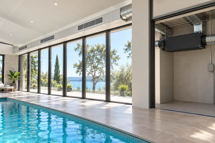
Integrate Ceiling Distribution With Dehumidification Equipment
Select the humidity-control approach after establishing loads and air paths. Mechanical dehumidification, conditioned ventilation, or combined equipment each creates different supply temperatures and operating sequences.
WetWells describes indoor pool dehumidifier integration options including ducted and perimeter distribution. Treat these as configuration possibilities requiring project-specific engineering, not verified performance outcomes.
Check moisture-removal performance at the project’s actual entering-air conditions. A published daily capacity may be measured at different temperature and humidity conditions than those in operation.
The equipment schedule should state design entering conditions, expected latent removal, sensible heating or cooling contribution, airflow, and fan capability against calculated external static pressure.
When Ceiling-Mounted Equipment Makes Sense
A ceiling-mounted dehumidifier can preserve floor space where structure, drainage, access, and available duct pressure permit. That mounting choice alone does not establish pool suitability.
For a pool environment, confirm material protection, electrical suitability, maintenance clearances, condensate handling, and compatibility with required ventilation. Avoid treating generic commercial applications as evidence of certified pool performance.
Large or complicated facilities may benefit from equipment in a service room with distributed ceiling ducts. Compare maintainability and acoustic separation alongside initial installation convenience.
Match the Fan to the Entire Duct Network
Calculate pressure loss through filters, coils, transitions, branch ducts, dampers, outlets, and return paths. Include dirty-filter conditions and any accessories in the selected configuration.
Verify the fan operating point against its performance curve. Extra duct length or restrictive grilles can reduce delivered airflow even when the equipment’s nominal airflow appears adequate.
Detail Ductwork for Humidity and Corrosion
Pool atmospheres expose ductwork and supports to sustained moisture and chemically aggressive conditions. Select materials, coatings, seals, fasteners, and accessible components for the actual exposure conditions.
Avoid assuming ordinary stainless steel, galvanized metal, or aluminum is automatically durable. Request material and coating guidance covering chemical exposure, cleaning procedures, and expected inspection needs.
Where duct surfaces might fall below surrounding dew point, provide suitable insulation with a continuous, sealed vapor barrier. Pay special attention to hangers, penetrations, seams, and connections.
Protect the building’s own air and vapor control layers where ducts cross the envelope. An otherwise effective supply layout cannot prevent hidden moisture damage through unsealed penetrations.
Plan condensate removal for cooling and dehumidification components, with correct trapping, slope, access, and overflow protection as required by the equipment configuration.
Allow technicians to inspect filters, coils, drains, diffusers, dampers, and connections without unsafe work above water. Service access is part of selection, not an afterthought.
Avoid Predictable Design Failures
A common response to damp glazing or complaints is increasing fan speed. Diagnose the airflow path and moisture source first; added velocity can worsen drafts and evaporation.
| Observed problem | Possible design fault | What to check before changing equipment |
| Wet glazing | Supply bypasses cold frames | Surface temperature, discharge angle, envelope details |
| Humid upper zone | Stratification or poor return location | High-level readings and supply trajectory |
| Drafts across water | Jet directed onto pool | Outlet angle, local velocity, diffuser selection |
| Odor near swimmers | Weak outdoor-air delivery or source exhaust | Water chemistry, capture path, operating airflow |
| Weak far-end airflow | Duct loss or imbalance | Branch flow, damper position, fan pressure |
| Pressure reversal | Uncoordinated exhaust and makeup air | Door conditions, control modes, leakage |
Changes should be evaluated across connected zones. Redirecting an outlet to protect one window may deprive another area of conditioned air or compromise pollutant removal.
A hypothetical example is a pool with clear upper glazing but damp lower frames. Investigate lower-surface temperature and supply coverage before specifying a larger dehumidifier.
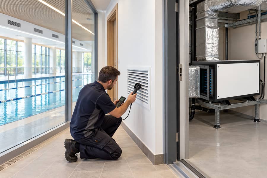
Commission the System Under More Than One Operating Mode
Commissioning should demonstrate that calculated airflow reaches the intended zones and that humidity, pressure, and contaminant removal remain coordinated when operating conditions change.
Start with construction checks. Confirm installed duct sizes and routing, diffuser orientation, corrosion protection, vapor-barrier continuity, drain connections, and access to balancing devices.
Measure Airflow and Air Patterns
Measure supply and return branches, outdoor air, and exhaust separately. Reconcile the results with approved schedules, fan operation, and intended pressure relationships.
Use smoke visualization or suitable airflow instruments where appropriate to identify ceiling short-circuiting and poorly served decks. Record water-adjacent velocities without disturbing swimmers or operations.
Measure representative occupied-zone temperatures and humidity at more than one elevation. Compare them with upper-level readings to identify stratification that a single wall sensor might miss.
Test Heating, Cooling, and Reduced-Flow Operation
Repeat air-pattern checks under heating and cooling conditions where available, because supply buoyancy affects throw. Test the lowest intended supply setting rather than assuming full-flow results apply.
Verify condensation protection at vulnerable glazing and frames against measured dew point and surface temperature. Where cold weather is unavailable, record the limitation and arrange seasonal follow-up.
Simulate permitted changes in occupancy mode, outdoor-air demand, and exhaust operation. Verify that pressure controls respond correctly while minimum required ventilation remains available.
Prepare a Usable Procurement and Handover Package
Give vendors the pool geometry, water conditions, operating schedules, envelope information, load calculations, duct drawings, and specified airflow duties. Request assumptions and exclusions in writing.
For final review, require the following deliverables rather than accepting a nominal moisture-removal number as proof of system suitability:
- Equipment selection: Performance at stated entering conditions, fan curve, external static pressure, and electrical requirements.
- Air distribution: Outlet schedules, heating and cooling throw data, balancing locations, and reduced-flow expectations.
- Materials and drainage: Corrosion protection details, duct insulation and vapor seals, condensate routing, and maintenance clearances.
- Ventilation and controls: Outdoor-air and exhaust sequences, pressure response, alarms, and defined safe failure behavior.
- Commissioning records: Measured airflows, pressure relationships, occupied-zone conditions, corrective adjustments, and outstanding seasonal tests.
Accept the installation only against agreed project-specific criteria. Record control settings and unresolved observations so operators can distinguish future equipment faults from air-distribution or envelope problems.