
Choose a ducted refrigerant dehumidifier when dry air must reach separated rooms, equipment must be concealed, or floor space is limited. Choose a standalone unit when one open area needs moisture control and accessible floor placement, power, and drainage are available.
Neither installation is automatically more effective or efficient. Both use refrigeration to condense moisture. The better choice delivers sufficient airflow and moisture removal throughout the required space while keeping drainage, noise, controls, and maintenance practical.
Compare Air Distribution Before Choosing the Cabinet
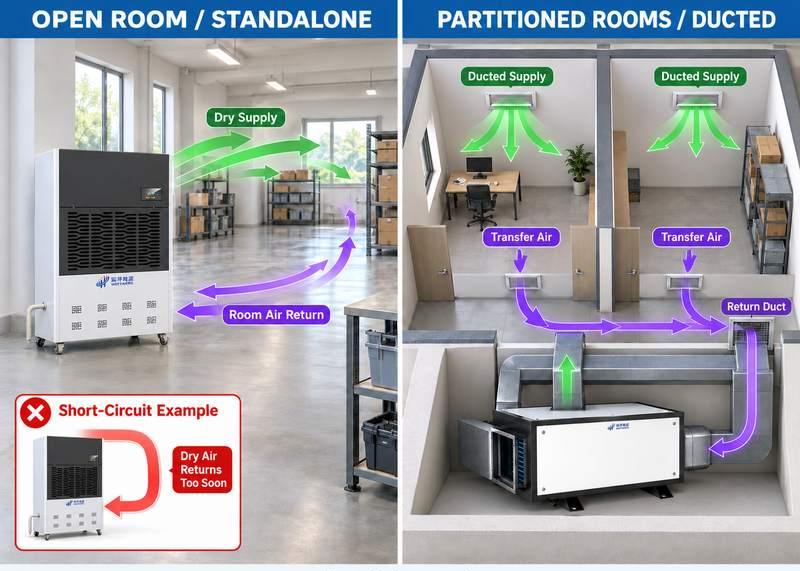
“Ducted” describes how air travels. “Standalone” here means a unit that draws from and discharges directly into the surrounding space, without distribution ductwork.
| Installation Factor | Ducted Arrangement | Standalone Arrangement |
| Air delivery | Through planned return and supply paths | Directly into the installation area |
| Typical advantage | Reaches selected rooms or remote locations | Straightforward access and local deployment |
| Space requirement | Equipment location plus ducts and service clearances | Floor footprint plus unobstructed inlet and outlet |
| Main distribution risk | Excess resistance or unbalanced branches | Obstructions and untreated pockets |
| Future changes | May require duct and control changes | Often easier to reposition within installation limits |
A ducted machine can sit in a plant room rather than above a ceiling. A ceiling-mounted machine still needs a complete air-distribution design.
WetWells’ custom refrigerant dehumidifier solutions allow discussion of structure, airflow, duct connections, controls, and drainage before a configuration is approved.
Compare Product References Under Matching Rating Conditions
These WetWells product pages provide useful starting points for an installation inquiry:
| Product Inquiry Page | Published Moisture Removal | Published Airflow | Installation Discussion |
| MCH-790B Commercial Dehumidifier | 90 L/day | 1,200 m³/h | Floor placement and open-room circulation |
| MCH-3.7G Ceiling-Mounted Dehumidifier | 90 L/day | 1,200 m³/h | Compact concealed installation and duct layout |
| MCH-7G Ceiling-Mounted Dehumidifier | 180 L/day | 2,400 m³/h | Larger air paths and service access |
| MCH-7480B Industrial Dehumidifier | 480 L/day | 5,600 m³/h | Floor space and circulation in large open areas |
The capacity ratings above use 30°C and 80% RH. Published airflow figures do not establish the airflow available against your proposed duct resistance.
The MCH-790B and MCH-3.7G share the same published removal capacity and airflow. Their different structures illustrate why installation must be evaluated separately from nominal capacity.
- Request performance at the actual inlet conditions and target RH.
- Confirm the selected model’s approved installation orientation.
- Obtain fan performance and connection drawings for any ducted proposal.
- Do not attach ducts to a standalone outlet without manufacturer approval.
Match the Installation to Rooms, Doors, and Obstacles
Room area alone cannot show whether air will circulate effectively. Room layout, storage, equipment placement, and closed doors can have a greater impact than overall floor space.
| Site Layout | Practical Starting Point |
| One open storage room | Standalone equipment with verified circulation |
| Several enclosed rooms | Ducted supply and a return or transfer path for each served area |
| Changing workshop layout | Accessible standalone units or an adaptable distribution design |
| Occupied rooms with limited floor space | Concealed ducted installation, subject to access and acoustic review |
| Rooms with different moisture targets | Separate zones or equipment with an agreed control strategy |
- Keep standalone inlets clear of walls, curtains, cartons, and machinery.
- Avoid placing the outlet where dry air immediately returns to the intake.
- For ducted systems, verify circulation with doors in their normal operating position.
- Do not combine spaces with incompatible air-quality requirements through a shared return.
Verify Airflow Against the Installed Duct Resistance
A ducted installation adds resistance through ducts, bends, branches, grilles, filters, and dampers. At the resulting operating point, the fan must supply the specified airflow.
- Define the required airflow for each served area.
- Calculate resistance along the relevant supply and return paths.
- Allow for the specified filter condition and other accessories.
- Check the proposed operating point against the manufacturer’s fan data.
- Verify and balance airflow after installation.
| Quotation Detail | Why It Matters |
| Airflow at stated external static pressure | Connects fan performance to the actual installation |
| Pressure measurement boundaries | Clarifies which internal or external losses are included |
| Filter condition | Identifies whether performance assumes clean or loaded filters |
| Duct and grille dimensions | Allows resistance and outlet-velocity review |
A flange size is a connection dimension, not proof that a particular duct length will work. Likewise, a total-pressure figure should not be treated as available external static pressure without clarification.
Decide Whether the Ducts Are Independent or HVAC-Connected
A dedicated duct system can circulate air independently of the building’s air conditioner. Connecting a dehumidifier to existing HVAC ducts introduces additional pressure and control interactions.
| Arrangement | What to Resolve |
| Dedicated return and supply ducts | Room coverage, balancing, and independent operation |
| Discharge into existing HVAC ductwork | Connection pressure and potential reverse airflow |
| Distribution dependent on the HVAC fan | Fan interlock, runtime, and additional energy |
| Shared return or supply paths | Air routing when either machine is off |
Ask the supplier to approve the exact connection diagram. Identify any required dampers and interlocks, then test the relevant fan combinations rather than assuming one connection method suits every building.
Ducting also does not automatically provide fresh air. Outdoor-air supply requires a suitable inlet, treatment capacity, controls, and a coordinated building air balance.
Plan Drainage Before Fixing the Equipment Position
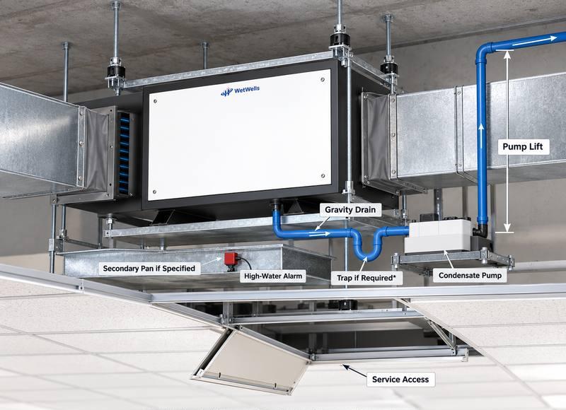
Both arrangements generate condensate. Above-ceiling placement makes the drainage route and response to leakage particularly important because water may damage finished areas below.
| Drainage Question | Standalone Installation | Ducted or Concealed Installation |
| Can water drain by gravity? | Check outlet and floor-drain elevations | Check the entire route before closing the ceiling |
| Is a pump required? | Verify lift and discharge resistance | Provide pump access and a fault response |
| Is a trap necessary? | Follow the model’s instructions | Account for drain-pan pressure and manufacturer requirements |
| What happens during a blockage? | Define high-water response | Assess secondary containment and overflow protection |
- Keep the unit level as instructed.
- Provide cleanout and drain-pan access.
- Avoid unsupported hoses that sag or become pinched.
- Confirm where alarm signals go and whether a drainage fault stops water production.
Evaluate Noise and Heat Where People Work
Moving the cabinet away from occupants can reduce direct equipment noise, but ducts can carry fan noise and vibration into rooms. Standalone units place the sound source directly in the served space.
| Concern | Installation Response |
| Compressor vibration | Suitable mounts, supports, and connection isolation |
| Air noise at grilles | Review outlet velocity and distribution layout |
| Duct-borne sound | Assess routing and appropriate attenuation |
| Warm supply air | Place outlets to avoid uncomfortable direct discharge |
In a conventional self-contained refrigerant system, dry air leaves warmer after condenser reheating. Ducting distributes that heat; it does not remove it from the building.
- Compare sound data with stated measurement distance and operating mode.
- Include any additional room cooling demand in the design.
- Confirm condenser arrangement where separate heat rejection is required.
- Check noise at the occupied location after installation.
Keep Sensors and Service Components Accessible
A hidden machine still needs routine attention. Filter removal, coil cleaning, drain inspection, and component replacement must remain possible after all ducts and finishes are installed.
| Item | What to Check |
| Humidity sensor | Measures representative air rather than a dry discharge plume |
| Filter | Can be removed without dismantling fixed building services |
| Electrical panel | Has the specified working and opening clearance |
| Drain pan and pump | Can be inspected and cleaned |
| Replacement route | Allows the unit or major components to be removed |
For a standalone unit, prevent later storage changes from blocking access. For ceiling installation, size the access opening for the service task, not just a visual inspection.
A shared return-air sensor may hide differences between rooms. Where humidity requirements are critical, agree measurement locations and assess whether separate zones need independent control.
Compare Total Installed Cost and Operating Duty
Standalone equipment often requires less distribution work, while ducted equipment may free useful floor space and serve locations that a nearby unit cannot reach directly.
Compare both proposals against the same moisture load, room coverage, operating hours, and acceptance target.
- Initial work:Equipment, ducts, grilles, supports, electrical supply, drains, and controls.
- Energy:Compressor, dehumidifier fan, any required HVAC fan, pumps, and associated cooling.
- Maintenance:Filter changes, access time, cleaning, and replacement parts.
- Continuity:Consequences of one central unit stopping versus several local units.
- Adaptability:Cost of moving standalone units or modifying duct branches.
Neither arrangement has an inherent efficiency advantage across all projects. Poor duct design can waste fan energy; poorly distributed standalone capacity can leave damp areas while nearby air is repeatedly treated.
Approve the Installation Through an Operating Test
The final decision should be supported by measurements throughout the served space.
| Acceptance Check | Evidence to Record |
| Moisture-control duty | Inlet conditions, target RH, occupancy, and process activity |
| Air distribution | Measured airflow and branch balance, where applicable |
| Room performance | RH and temperature at representative locations |
| HVAC interaction | Operation with the agreed fan and damper combinations |
| Reliability | Drainage, alarms, restart behavior, and service access |
Test with normal door positions and realistic obstructions. Record recovery after an agreed moisture disturbance, and inspect remote corners instead of relying on the controller display alone.
Choose standalone installation when local circulation can meet the duty reliably. Choose ducted installation when planned distribution solves a real coverage or space problem and the complete air path, drainage, controls, and maintenance provisions have been verified.