
Commercial refrigerant dehumidifiers usually prioritize practical moisture control, manageable noise, and convenient installation in occupied buildings. Industrial designs must also address process moisture, demanding operating conditions, equipment integration, and the consequences of interrupted drying.
Both use refrigeration to condense water from air. The meaningful differences lie in the operating duty, refrigeration circuit, airflow, heat handling, controls, and service provisions. Capacity alone does not define the category; a hotel pool may need more specialized equipment than a small workshop.
Compare the Design Duty Before the Machine Size
The following comparison describes common design priorities, rather than features guaranteed by either label.
| Design Question | Commercial Priority | Industrial Priority |
| What needs protection? | Occupants, interiors, furnishings, stored goods | Materials, machinery, production quality |
| Where does moisture originate? | Outdoor air, people, bathrooms, pools | Infiltration, wet materials, washing, process evaporation |
| What governs installation? | Floor space, appearance, noise, building services | Air distribution, process layout, utilities, maintenance access |
| What happens during a fault? | Comfort or building conditions deteriorate | Production or material quality may be affected |
| What needs customization? | Dimensions, placement, drainage, acoustics | Operating envelope, controls, heat rejection, protection |
For specification work, start with WetWells’ customizable refrigerant dehumidifier solutions, which offer capacity, airflow, structure, control, and drainage customization.
- Define the required humidity at the location that matters.
- Identify peak moisture generation and its duration.
- Record operating hours and allowable recovery time after doors open.
- Decide whether a shutdown requires an alarm, standby capacity, or production intervention.
Compare Capacity Under The Same Environmental Conditions
WetWells’ published standard-model data illustrate how capacity and electrical requirements change across the range.
| Model and Product Inquiry Page | Published Capacity at 30°C, 80% RH | Airflow | Published Supply |
| MCH-756B Commercial Dehumidifier | 56 L/day | 500 m³/h | 220 V, 50 Hz |
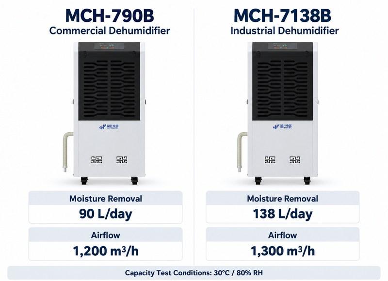
| MCH-790B Commercial Dehumidifier | 90 L/day | 1,200 m³/h | 220 V, 50 Hz |
| MCH-7138B Industrial Dehumidifier | 138 L/day | 1,300 m³/h | 220 V, 50 Hz |
| MCH-7480B Industrial Dehumidifier | 480 L/day | 5,600 m³/h | 380 V, 50 Hz |
These are published reference configurations; confirm the supplied configuration in the quotation.
- Request moisture-removal data at the actual inlet temperature and target RH.
- Compare liters per day only when rating conditions match.
- Include infiltration, ventilation, and process moisture in the load calculation.
- Treat the listed floor area as preliminary guidance; ceiling height and moisture generation can change selection substantially.
The MCH-790B and MCH-7138B have the same published cabinet dimensions, yet different capacities. This shows why cabinet size is a poor substitute for performance data.
Match Coil Design and Defrost to the Operating Envelope
A refrigerant dehumidifier needs an evaporator surface below the air’s dew point. At colder or drier conditions, moisture removal becomes more difficult, and frost can interrupt the useful drying period.
| Operating Condition | Design Requirement to Discuss |
| Normal-temperature room | Capacity and efficiency at the intended RH |
| Cold storage or winter operation | Coil temperature control, defrost strategy, drainage freeze protection |
| Hot workshop or drying room | Compressor operating limits, condenser performance, electrical cooling |
| Low target dew point | Whether refrigeration can achieve the duty economically |
WetWells lists 5°C–38°C operation for the standard models above. Its MCH-10DW Low Temperature Dehumidifier lists −2°C–38°C operation, but its 240 L/day rating is measured at 30°C and 80% RH.
- A minimum operating temperature does not establish capacity at that temperature.
- Ask for net removal over a complete drying-and-defrost cycle.
- Confirm defrost initiation, termination, and alarm behavior.
- For very low dew points, assess a desiccant or combined system rather than simply increasing refrigerant-machine size.
Design the Air Path and Heat Handling Together
Commercial installations often favor discreet air outlets and low noise near occupants. Industrial layouts may require delivery past racks, partitions, or equipment. Both need a return path that reaches the humid zones.
For concealed installation, the MCH-7G Ceiling-Mounted Dehumidifier provides published inlet and outlet flange dimensions. Discuss duct resistance and fan performance before finalizing a custom layout.
| Design Item | What to Verify |
| Ducted airflow | Required volume at the installed external static pressure |
| Room circulation | Supply and return locations, obstacles, short-circuit paths |
| Filtration | Pressure drop with a clean and loaded filter |
| Noise | Measurement distance, operating mode, installation conditions |
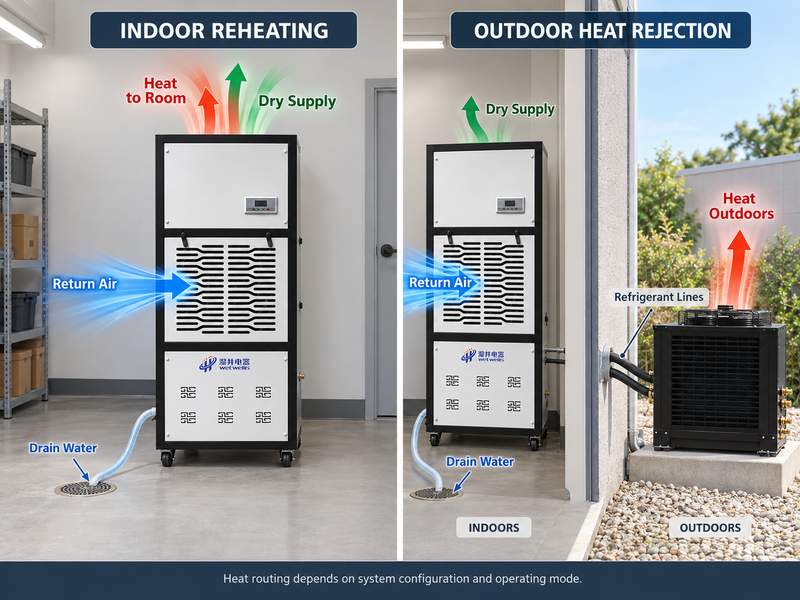
| Temperature control | Allowable room heat gain and route for rejecting heat |
A conventional self-contained unit returns warmer, drier air to the room. Where this heat is unacceptable, discuss separate heat rejection or coordinated cooling. WetWells’ MCH-10 Temperature Controlled Dehumidifier lists cooling, heating, and external static pressure data for that discussion.
Its capacity rating uses 30°C and 90% RH, so it cannot be compared directly with the 80% RH ratings above.
Specify Humidity Controls Beyond the Display Resolution
Commercial and industrial machines can both use automatic humidity control. Industrial projects more often need the humidity reading to trigger an action elsewhere in the facility.
| Control Detail | Why It Changes the Design |
| Sensor location | A return-air reading may differ from conditions around materials |
| Sensor accuracy | Determines measurement uncertainty |
| Start/stop differential | Affects cycling and humidity fluctuation |
| Compressor restart delay | Limits rapid restarts after stopping or power interruption |
| Alarm outputs | Allows staff or another system to respond to faults |
| Remote interface | Requires an agreed protocol and point list |
- Separate display increments, sensor accuracy, and room control tolerance.
- Agree where acceptance measurements will be taken.
- Define behavior after sensor failure, communication loss, and power restoration.
- Specify whether the fan runs continuously or stops with the compressor.
- Confirm which interfaces are included in the selected configuration.
A 1% RH adjustment step does not prove that every part of a room stays within ±1% RH. Tight process tolerances require sensor placement, air distribution, and load behavior to be considered together.
Build Drainage for Unattended Operation
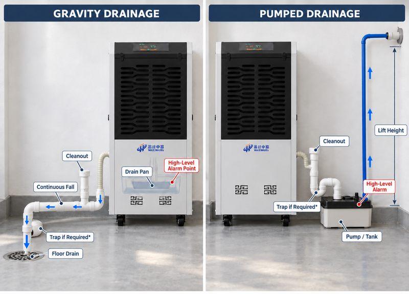
Continuous drainage is already listed for the commercial and industrial standard models compared above. It is therefore an installation requirement to examine, rather than an industrial-only feature.
- Check the route:Establish outlet height, drain destination, slope, and maintenance access.
- Match the method:Use gravity drainage where practicable; specify a pump where elevation requires it.
- Size for peak flow:Daily capacity divided by 24 is an average, not necessarily the peak drainage rate.
- Address pressure:For ducted equipment, follow the manufacturer’s trap requirements for the actual drain-pan pressure.
- Define fault handling:Confirm the response to a blocked drain, high water level, or pump failure.
- Protect cold sections:Identify where collected water or the drain line could freeze.
Choose Materials and Service Access for the Environment
An industrial label does not establish resistance to dust, chemicals, or washdown. Commercial pool environments can also be corrosive, while some industrial rooms are clean and temperature-controlled.
| Site Condition | Specification Detail |
| Dust or fibers | Accessible filters, coil-cleaning method, service interval |
| Corrosive atmosphere | Suitable coil protection, cabinet finish, fasteners, drain-pan materials |
| Frequent cleaning | Cleaning-agent compatibility and appropriate enclosure protection |
| Restricted access | Panel removal space and component replacement route |
| Hazardous atmosphere | Equipment suitability and certification for the specific classified location |
Ask for construction details and supporting documentation for the proposed unit. A coated cabinet does not establish coil protection, and a standard industrial unit should not be assumed suitable for a hazardous location.
- Confirm filter replacement without dismantling nearby services.
- Keep electrical components accessible after ductwork is installed.
- Obtain a spare-parts list and maintenance instructions.
- Allow physical access to remove the largest service component.
Evaluate Continuous Duty, Power, and Energy Together
Long operating hours can occur in both categories. The useful question is whether the proposed configuration can maintain the required condition throughout the actual duty cycle.
- Confirm voltage, frequency, phase, starting demand, and electrical protection.
- Identify compressor and fan limits at the hottest anticipated inlet condition.
- Request input power and moisture removal measured at matching conditions.
- Compare kWh per liter removed, then include fan, pump, and associated cooling energy.
- Account for defrost, cycling, and filter loading in expected operation.
- For critical duties, consider multiple units or standby capacity based on the permitted interruption.
A larger industrial machine may remove more water per hour, but that alone does not establish lower operating cost. Conversely, several small commercial units can introduce more drains, service points, and uneven control across one production space.
Approve a Configuration Against a Written Design Brief
The commercial-versus-industrial decision becomes useful when it leads to a specific equipment schedule and acceptance plan.
| Information to Provide | What the Supplier Should Confirm |
| Room volume, layout, door activity | Moisture-load assumptions and air distribution |
| Minimum/maximum temperature and target RH | Capacity at design conditions and operating limits |
| Process moisture and working schedule | Peak duty, recovery time, continuous-duty suitability |
| Ducts, drains, utilities, access | Installation drawing and connection requirements |
| Control tolerance and fault response | Sensors, control sequence, interfaces, alarm functions |
| Materials and environmental exposure | Construction, protection, maintenance provisions |
Before acceptance, test humidity at representative locations during normal work and the agreed peak load. Record temperature, RH, power, drainage behavior, and recovery after a defined disturbance.
Select the design that meets this brief with documented performance. For an occupied building, that may be a compact commercial unit; for a demanding process, it may require customized refrigeration, airflow, heat rejection, and controls.