
A refrigerant dehumidifier cools moist air to condense water vapor, then drains the collected water. In a conventional self-contained unit, the air then crosses a warm condenser coil and returns to the room drier and usually warmer.
Inside the sealed refrigeration circuit, refrigerant repeatedly passes through the compressor, condenser, expansion device, and evaporator. This cycle moves heat; the water collected in the drain comes from the air, not from the refrigerant.
Separate the Air Path from the Refrigerant Circuit
Two flows operate together, but they do not mix. Air travels across the outside of the coil tubes; refrigerant circulates inside them.
| Path | Typical Sequence | What Changes |
| Room air | Intake filter → evaporator → condenser → supply outlet | Temperature and moisture content |
| Refrigerant | Compressor → condenser → expansion device → evaporator → compressor | Pressure, temperature, and liquid/vapor state |
| Condensate | Evaporator surface → drain pan → tank or drainage system | Water leaves the treated space |
The fan’s physical position varies by design. A remote-condenser system also changes where heat is rejected, so the room air need not pass over an indoor condenser.
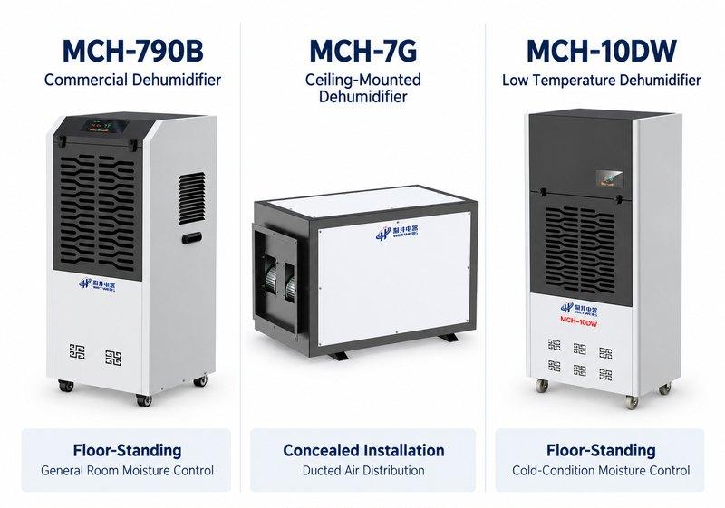
WetWells’ custom refrigerant dehumidifier range offers different airflow, structural, drainage, and control configurations. Relevant product inquiry pages include:
- MCH-790B Commercial Dehumidifier: a floor-standing reference for general room moisture control.
- MCH-7G Ceiling-Mounted Dehumidifier: a reference for concealed installation and duct connections.
- MCH-10DW Low Temperature Dehumidifier: a starting point for discussing cold-condition operation and defrost requirements.
Step 1: Refrigerant Pressure Is Increased by The Compressor
Low-pressure vapor from the evaporator enters the compressor, where its pressure rises before it flows to the condenser. The discharged vapor has a higher pressure and temperature, allowing it to reject heat at the condenser.
| At the Compressor | Refrigerant Condition |
| Inlet | Low-pressure vapor, normally superheated |
| Compression | Electrical energy drives mechanical work |
| Outlet | Hot, high-pressure vapor |
- The compressor circulates refrigerant; it does not pull room air through the machine.
- The fan provides the air movement across the heat exchangers.
- Normal operation requires vapor at the compressor inlet; liquid carryover can damage the compressor.
- Compressor capacity must be matched to the coils, metering device, refrigerant, and operating envelope.
“Superheated” means that the vapor is above its saturation temperature at the measured pressure. This does not always mean the suction pipe will feel hot when touched.
Step 2: The Condenser Releases Heat and Forms Liquid
Hot refrigerant enters the condenser and transfers heat to a cooler medium, commonly air. As heat leaves, the refrigerant changes from vapor to liquid while remaining on the high-pressure side of the circuit.
- Desuperheating:The hot vapor cools toward its condensing temperature.
- Condensation:Vapor becomes liquid as it releases heat.
- Subcooling:Where provided by the design, the liquid cools further below its saturation temperature.
The condenser releases both the heat absorbed by the evaporator and the energy supplied by the compressor. In a standard room-return unit, that heat reheats the air already cooled and dehumidified at the evaporator.
| Condenser Arrangement | Where the Heat Goes |
| Self-contained indoor condenser | Back into the treated room through the supply air |
| Remote condenser | To a separate location, commonly outdoors |
| Configurable temperature-control system | According to the selected circuit and operating mode |
Where room temperature also needs control, discuss the required heat-rejection arrangement through the MCH-10 Temperature Controlled Dehumidifier product inquiry page. Confirm the proposed piping and control sequence rather than assuming every mode uses the same air path.
Step 3: The Expansion Device Reduces Pressure
High-pressure liquid refrigerant passes through a restriction before entering the evaporator. The pressure falls, some liquid flashes into vapor, and a colder liquid-vapor mixture enters the low-pressure side.
| Metering Device | Basic Function |
| Capillary tube or fixed restriction | Meters flow through a fixed passage |
| Thermostatic expansion valve | Adjusts flow in response to evaporator-outlet superheat |
| Electronic expansion valve | Adjusts flow using a controller and sensor inputs |
- Not every refrigerant dehumidifier has an adjustable expansion valve.
- The device meters refrigerant; it does not remove moisture from room air directly.
- Expansion lowers the evaporation temperature; the evaporator absorbs most of the heat.
- Valve type alone does not establish drying performance or energy efficiency.
The selected device must work with the compressor and heat exchangers across the intended load range. An expansion valve is a refrigeration component, not the user’s humidity-setting control.
Step 4: The Evaporator Absorbs Heat While Moisture Condenses
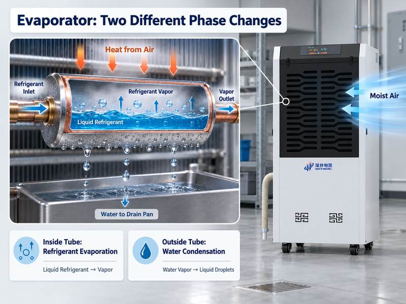
Inside the evaporator tubes, low-pressure refrigerant absorbs heat and boils. Outside the tubes, humid air loses heat to the cold coil surface.
These are two different phase changes:
| Substance | Location | Change |
| Refrigerant | Inside the evaporator tubes | Liquid evaporates into vapor |
| Water from room air | On the outside of the cold coil | Vapor condenses into liquid |
- Cooling initially lowers air temperature without necessarily removing water.
- Water droplets form on the coil as moisture in the incoming air condenses where the surface is cooler than the air’s dew point.
- Droplets collect on the fins and move into the drain pan.
- After absorbing heat in the evaporator, the low-pressure refrigerant vapor travels through the suction line back to the compressor, completing the refrigeration cycle.
Air leaving the evaporator contains less water vapor, but its relative humidity can still be high because it is cold. Not all air reaches the coil surface temperature; coil geometry and airflow affect the leaving-air condition.
Step 5: Drainage Carries the Collected Water Away
Condensation is useful only if the water can leave the equipment reliably. Standing water, overflow, or re-evaporation can reduce the practical benefit of drying.
| Drainage Method | Installation Requirement |
| Collection tank | Access for emptying and a functioning full-tank response |
| Gravity drain | Suitable outlet elevation, continuous fall, and a clear discharge route |
| Pumped drain | Pump duty matched to lift and piping resistance, with appropriate fault response |
- Keep the unit level as instructed so the drain pan empties correctly.
- Provide access to clean the pan and drain line.
- Where pan pressure requires a trap, follow the manufacturer’s arrangement and dimensions.
- Define the alarm or shutdown response to high water level or pump failure.
- Protect drainage sections that could freeze in cold operation.
The condensate outlet is separate from the sealed refrigerant circuit. Neither normal water collection nor tank emptying consumes refrigerant.
Step 6: Reheating Lowers Supply-Air Relative Humidity
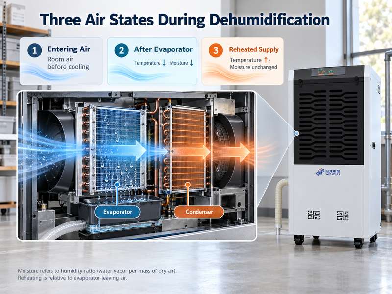
After the evaporator removes water, a conventional unit passes that air across the condenser. Reheating raises its temperature without deliberately adding water vapor.
| Air Treatment Stage | Temperature Trend | Moisture Trend |
| Initial cooling | Falls | Humidity ratio initially stays approximately constant |
| Cooling with condensation | Falls | Humidity ratio decreases |
| Condenser reheating | Rises | Humidity ratio stays approximately constant |
- Humidity ratiodescribes water-vapor mass relative to dry-air mass.
- Relative humidityalso depends on temperature.
- Reheating reduces RH at essentially unchanged moisture content; the evaporator performs the water removal.
- Warm discharge air is therefore expected from many self-contained dehumidifiers.
An air conditioner can also condense water at its evaporator. The main distinction here is heat handling: ordinary air conditioning rejects condenser heat elsewhere, whereas a self-contained dehumidifier returns it to the room.
Understand What the Humidity Controller and Defrost System Do
The refrigeration cycle runs when drying is required and operating conditions permit. Controls decide when to start, pause, protect, or restart it.
| Control Function | What It Does |
| Humidity demand | Calls for drying when the measured RH exceeds the configured threshold |
| Start/stop differential | Limits repeated switching around the setpoint |
| Restart delay | Prevents immediate compressor restart where specified |
| Defrost | Removes evaporator frost that restricts airflow and heat transfer |
| Protective alarm | Responds to the faults monitored by the selected model |
During defrost, normal moisture removal may pause or change. Fan behavior and defrost method vary by machine; do not assume that a running fan means the compressor is actively drying.
Sensor location also matters. A reading near the discharge outlet may not represent humidity around stored materials or across a large room.
Explain Why Actual Water Collection Changes
The same machine can collect different amounts of water as conditions change. A catalog rating is tied to its test temperature and RH, not a guaranteed daily yield.
| Changing Condition | Effect to Consider |
| Lower inlet temperature | Can reduce available condensation and increase defrost time |
| Lower inlet humidity | Reduces the moisture available for removal |
| Dirty filter or coil | Changes airflow and heat transfer |
| Open doors or outdoor-air supply | Adds moisture load that can keep the machine running |
| Approaching the target RH | Usually reduces extraction as the air becomes drier |
For example, WetWells publishes the MCH-790B at 90 L/day under 30°C and 80% RH conditions. That figure does not predict collection at a cooler, drier operating point.
Request capacity and input-power data together at the design condition. Compare energy per liter removed using matching test conditions, and include defrost and auxiliary equipment where relevant.
Turn the Cycle Explanation into a Useful Equipment Specification
Each part of the process creates a question for equipment selection:
- Air intake:What airflow is required, and what duct resistance must the fan overcome?
- Evaporator:What capacity is available at the actual temperature and target RH?
- Refrigeration circuit:Is the selected configuration suitable for the full operating range?
- Condenser:Can the room accept the heat, or is separate heat rejection required?
- Drainage:Where will water discharge, and what happens if drainage fails?
- Controls:Where is humidity measured, and what tolerance and fault response are needed?
Provide room volume, moisture sources, temperature range, target RH, operating schedule, and installation constraints with the inquiry. Ask the supplier to identify the proposed configuration and its performance conditions in writing.
A successful installation keeps all three paths working together: air reaches the cold coil, refrigerant moves heat through the closed circuit, and collected water leaves through the drain.